Introduction:
SPI allows full-duplex, synchronous, serial communications with peripheral devices. Software can either poll the SPI status flags or SPI operation
can be interrupt driven.
Features:
- Communication between SPI and external device is always synchronous.
- SPI is interfaced with external peripheral device for data transfer.
- SPI can transfer data to an external peripheral device.
- SPI can receive data from an external peripheral device.
- SPI can work in master or slave mode.
- In master mode, SPI clock drives the slave peripheral.
- In slave mode, the external clock drives SPI.
SPI Interfacing with a device:
MOSI:
Master
Out Slave In - Output from SPI, connected to Serial Data Input of the peripheral
device.
MISO:
Master
In Slave Out - Input to the SPI, connected to Serial Data Output of the peripheral
device.
SCLK:
Clock
output from the SPI to the clock input to slave.
SS:
Chip select output from the SPI - master selects the chip with
which it wants to communicate.
Single master, single slave SPI implementation:

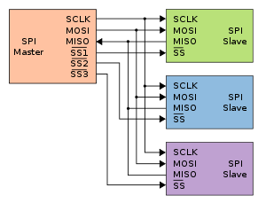
Single master, multiple slave SPI implementation:

Data Transfer mechanisim:
- The software module begins an SPI transmission by writing a byte to the SPI transmit data register.
- This byte is transferred to the shift register, when SPI transmit data register becomes empty the byte begins shifting out a bit at a time on the MOSI pin synchronized with the master clock signal.
- The transfer will continue for 8 clock cycles, transferring all 8-bits.
- The transmission ends when the whole byte is shifted out of the master SPI shift register and into the slave shift register.
- If SPI is receiving, the incoming byte will come to the shift register from the MISO pin.
- When one complete byte is received by the shift register, byte is copied to receive data register.
Thanks for reading !!!
All the Best !!!
Regards,
Saravana